| Overview |
| Principles of Dielectric Analysis |
| Use of Dielectric Measurements |
| Test Variables |
This topic covers the overview and theory of dielectric measurement. For additional information, refer to the following:
Dielectric analysis measures the electrical properties of a material as a function of time, temperature, and frequency. The parameter used to describe the interaction of the material with an electric field is the permittivity.
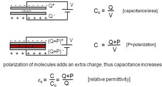
When a voltage is applied across two capacitor plates separated by free space, the charge accumulated at the plates divided by the applied voltage is referred to as the capacitance at free space Co.
With a material inserted between the plates, an extra charge is added to the capacitance C due to the polarization of the molecules of the material. The ratio of the capacitance C and capacitance in free space Co is the relative permittivity.
In dielectric tests, the following two fundamental electrical characteristics of a material are measured:
When correlated to the activity on the molecular level of a material, these properties allow probing the chemistry and molecular relaxation of polymers, composites, etc.
In a dielectric analysis, the sample is typically placed between two flat electrodes (parallel plate method); a sinusoidal voltage is then applied, creating an alternating electric field which polarizes the sample. The polarization oscillates at the same frequency as the electric field, but with a phase angle shift. The phase shift is measured by comparing the applied voltage and measured current. As such, the permittivity is a complex number and includes a conductive and a capacitive term. Usually, the results of a dielectric measurement are reported relative to the permittivity at free space eo (8.85e–12F/m). The complex relative permittivity is defined as  .
.  is also referred to as the dielectric constant of a material.
The measured capacitance Cp is used to calculate the permittivity. In a typical setup, the capacitance is evaluated using an equivalent parallel circuit, as shown in the image below. Gp = 1/Rp is the conductance, and Cp the capacitance.  is the admittance, and D is the dissipation.
Introducing the free space capacitance Co, the equation for the admittance can be written as:
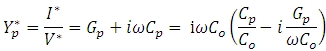
The relative complex permittivity consists of a capacitive and conductive term according to:
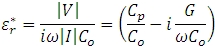
Replacing Co with the permittivity at free space 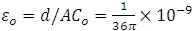 leads to the working equations for the real and imaginary parts of the complex permittivity:
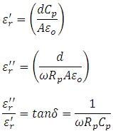
Rp is the resistance, Cp the capacitance of the equivalent parallel circuit, d is the sample thickness, and A the electrode area.
When the impedance of the sample  , a serial circuit (shown in the figure below) is preferred as it allows a more accurate determination of the capacitance.
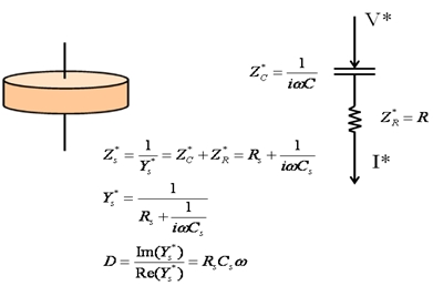
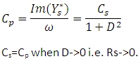
If a serial circuit is chosen for evaluation of the measurement, the capacitance Cp can be obtained from the admittance  assuming an equivalent parallel circuit according to:
The current can be measured by a low impedance current meter or by using the current to charge a load capacitor and measure the voltage across this capacitor. The Agilent LCR Meter performs the measurement of the capacitance Cp or Cs and the dissipation D or loss tangent; TRIOS calculates the permittivity e' and loss factor e''.
The real part of the complex permittivity e' is proportional to the capacitance and measures how much energy of the electric field is stored in the material. The imaginary part of the complex permittivity e'' is the loss factor and represents how much energy is dissipated or lost to the electric field.
Dielectric measurements are most sensitive to dipoles in the material. A dipole is a chemical bond that has an unbalanced distribution of charge in a molecule. Materials with a high dielectric constant have permanent dipoles due to the difference in charge distribution of the bonded atoms (e.g., carbonyl bond C=O, C-N). The electrical field also induces dipoles which cause a redistribution of the electrons shared between bonded atoms. The permittivity e' measures the contributions due to the induced dipoles e∞and due to the alignment of the permanent dipoles es , the loss factor e'' is a measure of the energy required to align the dipoles and to move ions across the sample (ionic conductivity).
The classical Debye equation describing the relaxation in polymers has a real and imaginary permittivity as follows:
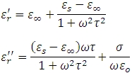
s is the ion conductivity, es is the permanent dipole permittivity, and t is the molecular relaxation time.
 is low for polymers at low temperature below the thermal transition because the molecules are frozen in place and cannot move to align themselves with the electrical field. Dielectric relaxations of the permanent dipoles contribute to in the frequency region associated with their molecular dynamics at the selected temperature.
Ionic contribution is not significant in  until the polymer becomes fluid (e.g., above the glass transition Tg or melting point Tm). Above Tg (and also at low frequency), the ionic conductivity dominates and can be used to follow changes in a material. Ionic conductivity is related to the viscosity, because fluidity is identified by the ease with which ionic impurities can migrate through a sample.
Dielectric measurements are used as an investigation tool to characterize a wide variety of materials to study polymer resin flow and cure, thermal transitions, extend of oxidation, and thermal breakdown.
The LCR Meter provides the capacitance C and the dissipation factor D or loss tangent tandDE. TRIOS software calculates and provides the following variables:
 (pF/m)
